1. The diameter of the waterway
Conventional cooling water circuits made using drilled holes typically have a diameter of 7/16 inches (approximately 11.11 mm). Cooling circuits made in this way, if they are too large in diameter, may cause the waterway to be inaccessible to the mold surface while avoiding the mold parts. If the diameter is too small, bit drift may occur during water processing. Although additive manufacturing technology circumvents some of the limitations of drilling methods, designing the waterway still requires setting the diameter within the empirically verified, common size range, thereby reducing the uncertainty of this technology.
2. Cross-sectional area
When the cooling waterway is processed by drilling, the cross-sectional area of ​​the waterway remains constant. Although 3D printing technology can produce a waterway with many different shapes, when designing a 3D printing conformal cooling waterway, the cross-sectional area of ​​the waterway should be kept constant to ensure that a constant volume of cooling liquid passes through the waterway.
3. The distance from the mold surface
There is no fixed rule for the distance between the cooling water circuit and the mold surface. For example, some companies keep the distance in the design exactly equal to the distance of the water path diameter, and some companies reserve the distance of 2 times the water path diameter.
For most conformal cooling circuits, the distance to the mold surface depends on the geometry of the part. When designing the distance from the mold surface, there is a principle that should be followed in order to maintain the same distance between the follow-up waterway and the mold surface, so as to achieve a uniform cooling effect.
4. Length of cooling waterway
When using the drilling method to process the cooling water circuit, if the debris generated during drilling is not emptied, bit drift or damage may occur. In this case, people will choose to design the cooling water circuit as short as possible.
Although there are no problems such as cutter damage due to the use of 3D printing technology to manufacture the conformal cooling water channel, it is not recommended to design the waterway too long during design. This is because the cooling water can enter and exit more rapidly in the shorter cooling water circuit, making the heat distribution more uniform.
5. Another rule of cross-sectional area
Because many short cooling water circuits can be cooled more evenly, some conforming cooling water circuits are designed according to the idea of ​​capillary tubes. That is, a large cooling water circuit is divided into multiple small and short waterways, and then Then import a large waterway. In this case, the sum of the cross-sectional areas of the multiple small waterways should be equal to the cross-sectional area of ​​the inlet and outlet of the large waterway, so as to ensure the uniform flow of water and further reduce the risk of warpage.
6. Rotary structure
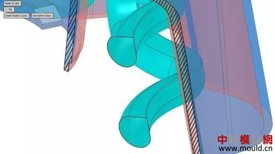
The amount of water in the mold cooling water circuit is a factor that affects the cooling time of the mold. The larger the water volume, the shorter the cooling cycle time. Another influencing factor is water turbulence. Although the inner surface of the 3D printing profile cooling water circuit is not polished, some turbulence is generated, but more turbulence can be generated if the rotating structure is added at the time of design.
The above design rules are not all the rules that need to be paid attention to in a successful 3D printing with a cooling water circuit. Moldmakers have a systematic understanding of injection mold manufacturing when designing a 3D printed cooling water circuit. There are many lessons to be learned from the traditional mold cooling water circuit design principles. These experiences are the basis for the effective design of 3D printing conformal cooling water circuits.
Lpg Tanker Truck,Lpg Truck,Lpg Gas Tanker Truck,Lpg Tanker Semi Trailer
ChengLi Special Automobile Co.,LTD , https://www.chenglispecialautomobile.com.cn