introduction
Ultrasonic waves carry information on the flow rate of the fluid when it travels in a flowing fluid. Therefore, the flow velocity of the fluid can be detected by the received ultrasonic wave and converted to flow. According to the detection method, it can be divided into different types of ultrasonic flowmeters such as the differential propagation velocity method, Doppler method, beam offset method, noise method, and correlation method.
Ultrasonic flowmeter is a kind of non-contact type instrument that has been applied only with the rapid development of integrated circuit technology in the past ten years. It is suitable for measuring fluid that is difficult to contact and observe, and large-diameter flow. It works in conjunction with a water gauge to measure open flow. The use of ultrasonic flowmeters does not change the flow state of fluids without installing measuring elements in the fluid, and does not produce additional resistance. The installation and overhaul of the instrument can be performed without affecting the operation of the production pipeline and is thus an ideal energy-efficient flowmeter.
First, the status quo
Recently I had a heating process pipe section, using a V-cone flowmeter to measure the supply and return flow. When the daily flow was found to be 1000 T/h during operation, the instantaneous deviation of the supply and return water could reach 200-300 T/h. This means that the daily loss of water reaches 7200T. This is unacceptable to any operating unit. Both suppliers and buyers have great differences in the accuracy of the watch. However, due to the fact that during operation, it is not possible to remove the flowmeter for verification. This problem, we designed a dual ultrasonic flow meter online comparison program, through the actual operation and data acquisition and analysis, for both parties to provide a scientific basis for subsequent processing.
Figure 1 shows the measurement system diagram for this section of the pipeline. The system uses the enthalpy difference method to measure the heat supply. The water supply enthalpy measuring unit is composed of a V-cone flowmeter and a temperature probe on the water supply pipeline, and the measured data enters. The heat totalizer uses a V-cone flowmeter and a temperature probe on the return line to form a backwater enthalpy measurement unit. The measured data goes into the calorimeter. The calorimeter calculates the supply and return water through regular sampling. The difference in enthalpy is used to calculate the amount of heat consumed by the heated end.

Figure 1 Structure of the measurement system
In the actual measurement process, the flow rate measured by the supply and return flow meters will be biased, that is, the system will lose water. If this loss of water is reasonable within the normal range, the impact on the measurement will not be great, but if A large deviation in the real-time flow value of the return water will not only affect the normal metering of the instrument but also reflect the excessive water loss during system operation. This is the focus of supply and difference of opinion between the two parties in trade measurement.
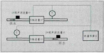
Figure 2 double ultrasonic flow meter measurement diagram
Second, double ultrasonic online measurement
In order to solve the above problems and eliminate doubts about the existence of metering devices, we have designed a dual-inline ultrasonic measurement and comparison scheme. The measurement method is shown in Figure 2. The location of ultrasonic flowmeters should be selected on the upstream side of the V-cone flowmeter. This ensures that there are enough straight sections and that the development of the flow rate is adequate and will not be interfered by downstream temperature sensors. Because the flow rate changes on the downstream side is relatively large, it is not conducive to the detection of ultrasonic flowmeters.
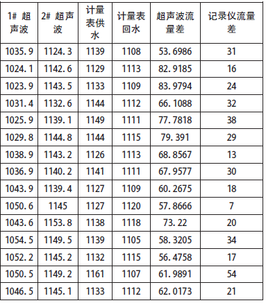
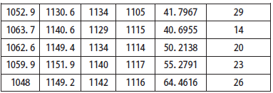
Based on the above considerations, we chose to test at about 2 o'clock in the afternoon. In order to record the accuracy of the data, we used two cameras to photograph the data display at the same time. Finally, we summarized the recording methods to avoid the data recording process. Deviations occur. We collected some valid data through measurement. See Table 1 for details.
Table 1:
Road Maintenance Truck including hot and cold pothole pather .
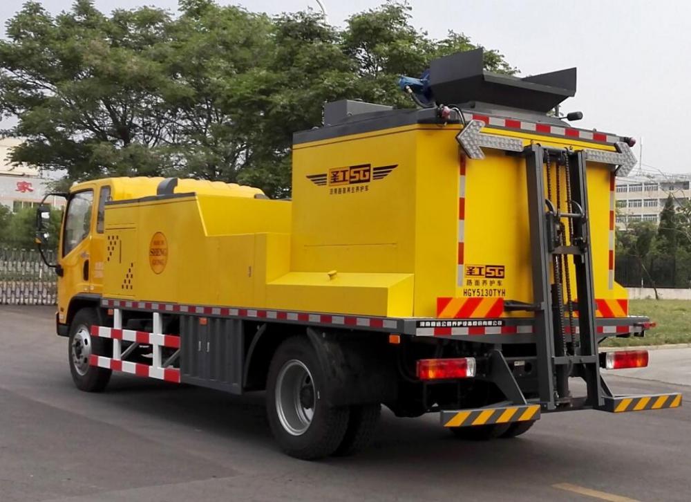
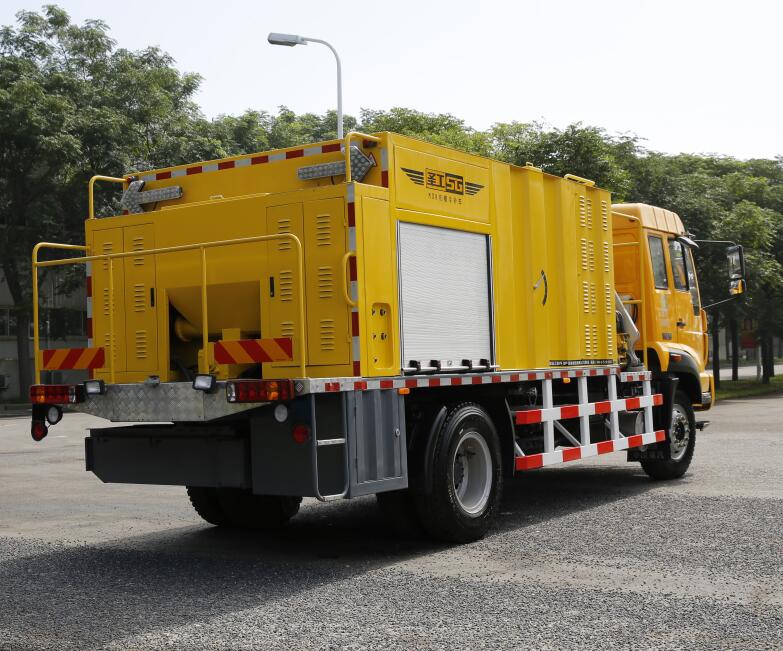
its working principle is to aggregate, cement, water, emulsified asphalt according to certain proportion to the mixer, the rapid mixing to form a composite Organic hydraulic material , the technology is the emulsified asphalt and other Organic materials with inorganic binder such as cement by the macroscopic and mesoscopic compound formed by road construction materials.
Road Maintenance Truck,Slurry Seal Truck,Road Repair Truck,Asphalt Emulsion Spray Truck
Henan Gaoyuan Road Maintenance Equipment Co., Ltd. , https://www.sgroadmachinary.com