
Edited by Yoganantham Natrayan, Engineer at Technical Support Team, Moldex3D

- Customer:Â Chemnitz University of Technology
- Country:Â Germany
- Industry:Educational / Academy
- Solution: Moldex3D Advanced Package; Flow, Pack, Cool, Fiber, Designer BLM
Chemnitz University of Technology was founded in 1836 as Royal Gewerbschule Chemnitz (Royal Mercantile College) in Chemnitz, Germany. Renamed in 1963, Chemnitz University of Technology is currently the third-largest university in Saxony with more than 10,000 students enrolled. (Source: www.tu-chemnitz.de)
Executive Summary
The flow behavior of thermoset materials in the injection molding process has not been adequately explained before. Therefore, the existence of the wall slip phenomenon between the thermoset plastics and the wall surface during filling remains unknown. This project demonstrates how Moldex3D helped a Chemnitz University of Technology student develop a useful method to study the wall slip phenomenon of the polymer during the filling stage and how to generate a material data sheet that can be directly imported into Moldex3D’s Material Database to simulate the injection molding process of thermoset materials with wall slip boundary conditions.
Challenges
- To investigate the wall slip phenomenon of thermoset materials during the filling
- To create a material data sheet for thermoset injection molding simulation
- To predict the master curves of rheological and cure kinetics at multiple heating rates
Solutions
Firstly, the team performed experimental injection studies under different processing. It was found that there was a strong slip on the interface between the phenolic polymer and the mold wall surface, which was not found for the thermoplastic injection molding. Secondly, the rheological and thermal properties of thermoset injection molding compounds were measured successfully. After that, the team used the numerical method to create a material data sheet and predicted the master curves of viscosity and cure kinetics at multiple heating rates. Finally, the team imported the datasheet to Moldex3D’s Material Database to investigate the simulation results of the injection molding process considering the slip boundary condition. The experimental results showed that a strong slip was found on the interface between the thermosets and the cavity surface.
Benefits
- Validation of the influence of wall slip phenomenon on thermoset injection molding
- Compared the flow behavior between thermosets and thermoplastics
- Created material data sheet for the reactive injection molding simulation process
Case Study
Dr. Tran-Ngoc Tu, Researcher at Chemnitz University of Technology, investigated the flow behaviors of the thermoset plastic (Vyncolit X655 PF-(GF+Mineral) 80%) with slip conditions and studied about the interaction phenomena between the melt front and cavity wall surface during the filling. Fig. 1 shows the unsteady flow melt front of thermoset plastics.

Fig. 1 An unsteady flow front of the thermoset phenolic polymer (left) and the supposed flow characteristic of thermosets (right)
To investigate the slip phenomena, the researchers manually painted to make a mark in the cavity before each injection cycle. After being ejected from the mold, via analysis, the position of white color appeared on the surface of the molded parts, if the white mark position keeps the same location at the cavity surface shows no-slip occurs after the injection cycle completed. Â On the contrary, it means that there is an obvious wall slip between the polymer and the cavity surface. Fig. 2 shows the technical method of slip phenomena identification methods.
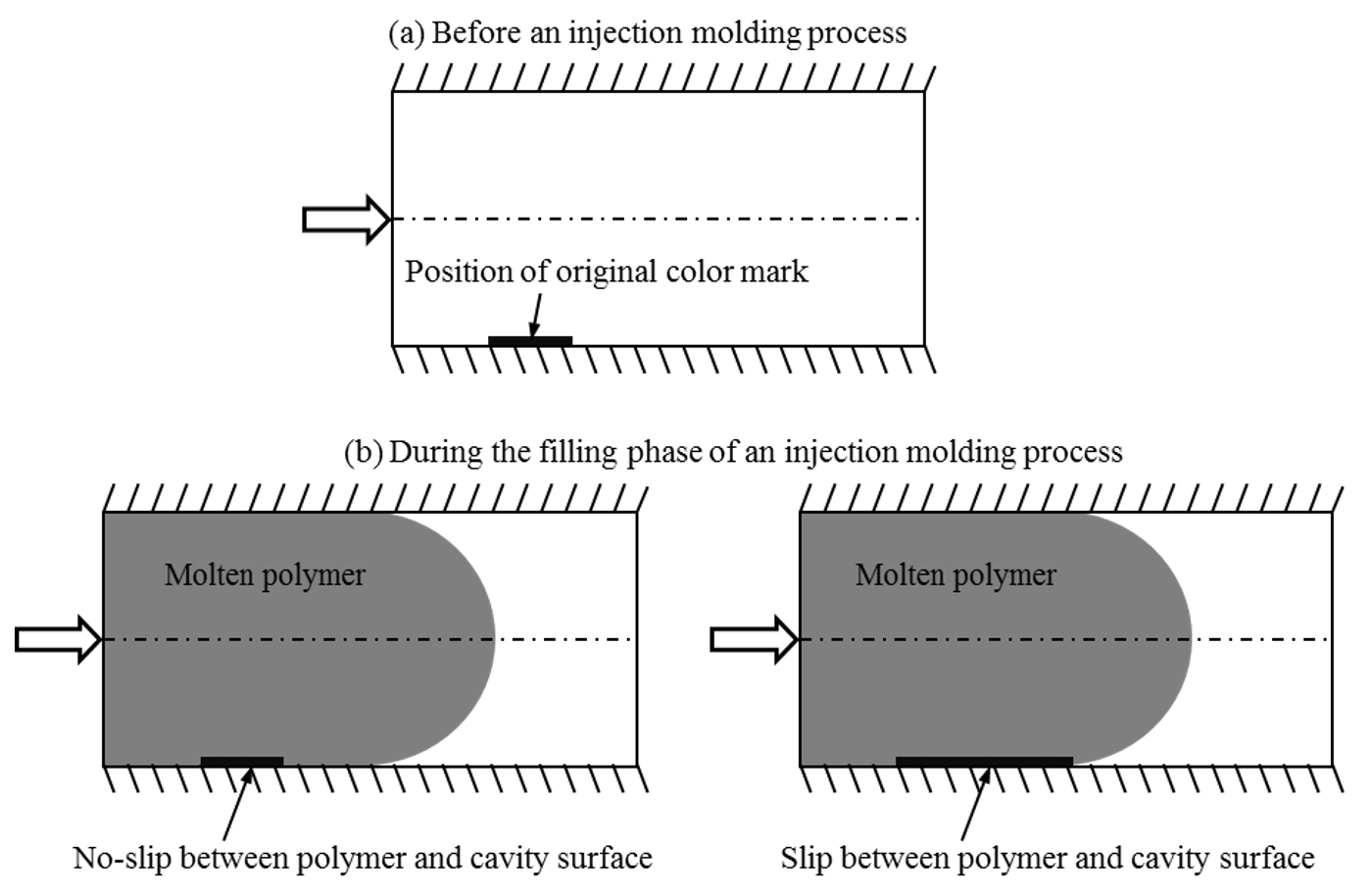
Fig. 2 The technical method of slip phenomena identification methods
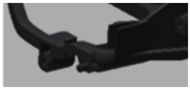
The researchers used the spiral and complex industrial part to investigate the slip phenomena, weld line location, and flow length. Fig. 3 shows the spiral part flow direction with a single injection speed profile. Fig. 4 shows the complex industrial part with the multi injection speed profile and Tables 1 & 2 show the process conditions of the spiral and complex parts.
 |
 |
|
||||||||||||
|
Fig. 3 Spiral part |
 |
Table 1 Spiral part process conditions |
Â
 |
 |
|
||||||||||||
|
Fig. 4 Complex industrial part |
 |
Table 2 Complex part process conditions |
Researchers observed from the spiral and complex parts, strong slip phenomena occur in the flow direction between the phenolic melt and cavity surface for all process conditions. The white mark trace was observed along the melt flow direction in the part surface. Fig. 5 shows the strong slip phenomena for both models.

Fig. 5 Slip of the white stripes on the cavity surface of a spiral and complex part
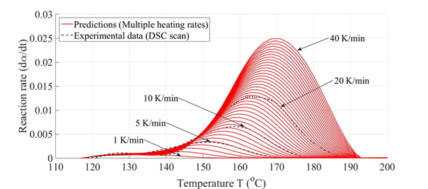
To predict the reality in the numerical simulations, the material properties are one of the important factors for injection molding numerical calculations. In this case, the researchers measured the thermal properties by using a differential scanning calorimeter (DSC Q2000) and thermal conductivity meter (DTC 300) and measured the rheological properties of the material by using a Plate-Plate rheometer (AR 2000). The measured data from instruments were used to develop the numerical model. The cure kinetics measured at three heating rates were 5, 10, and 20 k/min. The Kamal model (Cure kinetics model) used to predict different heating rates for reaction rate and degree of cure shows in Fig. 6 and 7 respectively.
 |
 | 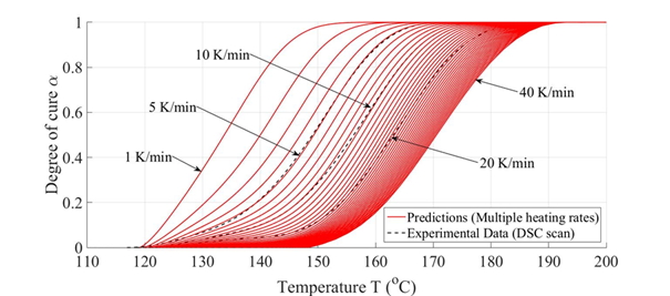 |
| Fig. 6 Reaction rate | Â | Fig. 7 Degree of cure |
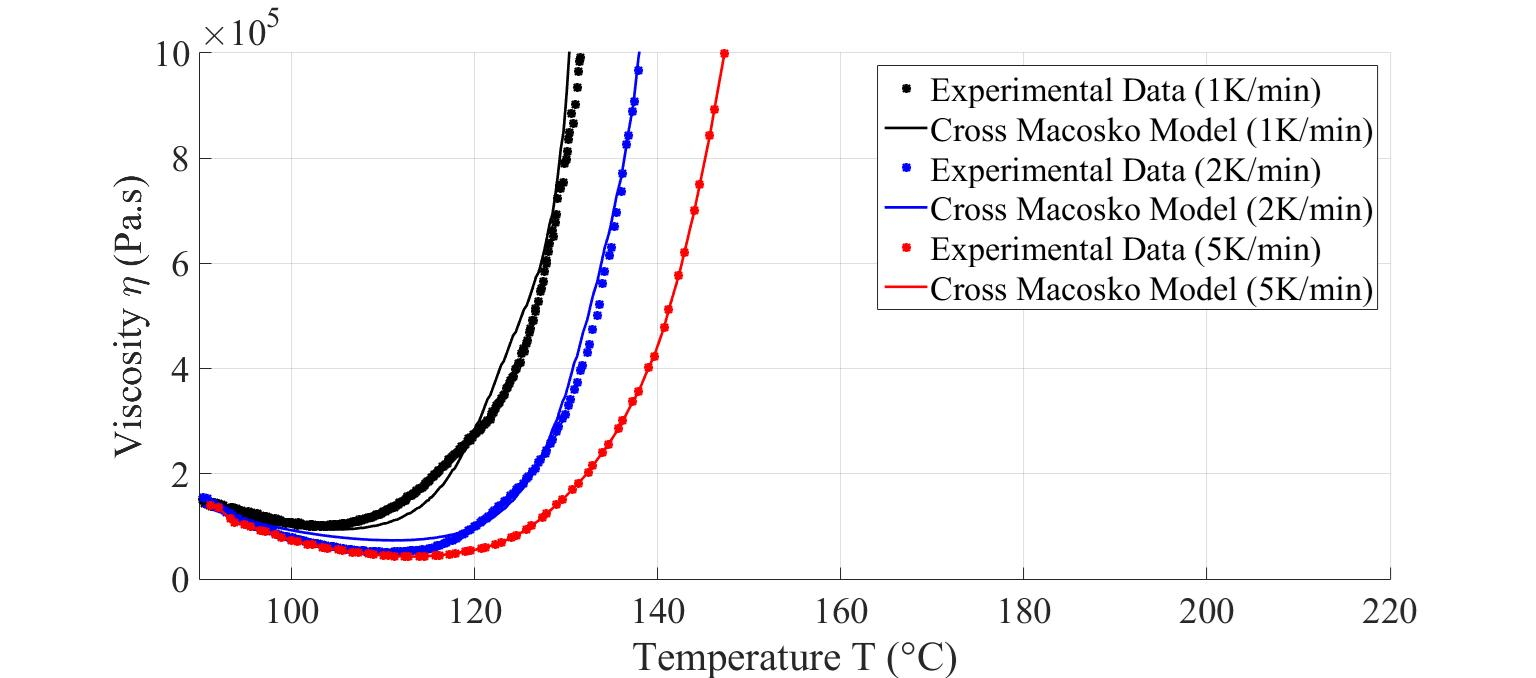
The Cross-Castro-Macosko model was used to predict the viscosity of the material with multiple heating rates. The predicted viscosity curves found good agreement result with the experimental data as shown in Fig. 8 and 9.
 |
 | 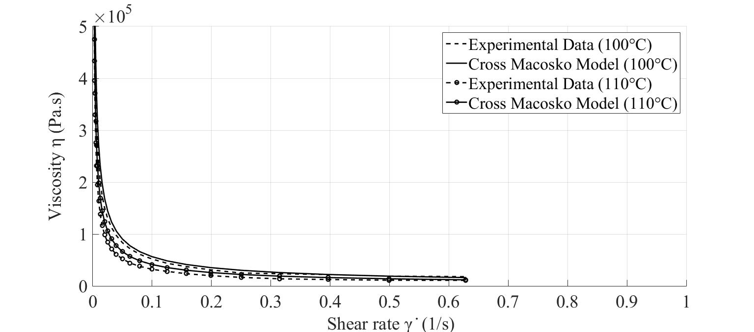 |
| Fig. 8 Viscosity over temperature | Â | Fig. 9 Viscosity over shear rate |
The researchers converted the predicted material properties into the material data format with the help of Moldex3D. Then, the material data file was imported into the Moldex3D Material database to predict the results. The researchers observed that the flow length results from Moldex3D and the experiment showed good agreement results with the slip conditions for the spiral part. For the complex industrial part, the different injection speed profiles were used in the experiment and simulation to observe the flow pattern behavior and the possible locations of the weld lines. Moldex3D shows short shot behaviorssimilar to the experiment of all different injection speed profiles. Researchers can observe the possible locations of weld lines from the incompleted (short shot) part (Fig. 10).
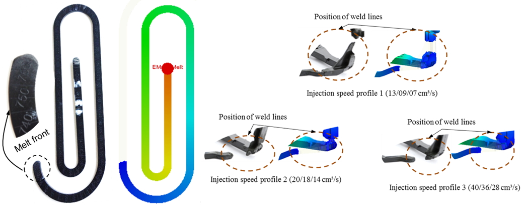
Fig. 10 Comparison between the incomplete injection-molded parts (left) and the corresponding filling patterns predicted by Moldex3D (right)
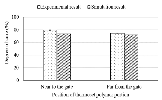
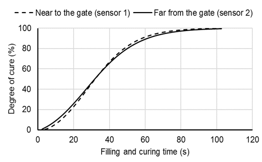
The experiment results for the spiral part shows that polymer near the gate has a higher degree of cure than polymer farther away from the gate. The prediction from the simulation at 43 seconds shows it around 75% with a difference of 4% lower than the experiment data (79%) from figure 11. From Fig. 12, the curing results show it only takes 50 seconds more for the molten core polymer to reach the cure degree of 79%. It shows that the material file used for the calculation is reasonable.
 |
 |  |
| Fig. 11 The comparison between the experimental and simulated cure degree of the spiral part (The filling and curing time is 43 s) |  | Fig. 12 The cure degree of the molten Vyncolit X655 in the filling and curing phase predicted by the simulation |
Results
Through Moldex3D analyses and the experiment, researchers observed the strong slip behavior between the cavity surface and thermoset polymer melt front. The researchers utilized Moldex3D to simulate the curing process of thermoset injection molding, flow length, pressure distribution, viscosity, weld line, and other parameters. Moldex3D shows good agreement with the experimental data. After considering all the results, Moldex3D is a perfect solution to predict the real scenario in the injection molding with the numerical calculations.
The Air Jet Mill is a highly efficient grinding equipment that utilizes high-speed airflow to achieve ultra-fine particle sizes. It is ideal for materials that are heat-sensitive, hygroscopic, or explosive. With precise control of airflow and grinding parameters, the mill ensures consistent particle size distribution and high grinding efficiency.
Flat Jet Mill Fot Industry,Flat Crusher Machine,Air Jet Mill Micronizer,Counter Air Jet Mill
Sichuan Shichuang Micro Nano Technology Co.,Ltd , https://www.scwnpowder.com